Sunday, June 9, 2013

Mark 4 build - step 6: Synchromesh

This step is fairly easy - attaching synchromesh cable to the rail effectors.


Vitamins:

  • 3  * Synchromesh pulley
  • 3  * 3mm grub screw (comes with pulley) 
  • 3  * 2 meter length of Synchromesh cable
  • 6  * 20mm long 1/8th inch heat shrink

RepRapped Parts :

Tools : 

  • 1.5mm hex key
  • lighter  (or a heat gun if you have one)

Assembly:
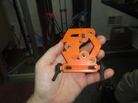
  1. Install the idler guide if you haven't already.
    1. Pop out the bearing
    2. Press the bearing all the way into the idler guide
    3. reassemble
  2. Loosen the idler slider - it should be as loose as it goes without falling out.
  3. Attach the pulleys to the motor shaft with the grub screws.
    1. Be sure to use the flat on the shaft, if your motor has flats.
    2. You might want to grind a flat if you don't have one.  Slipping pulleys sucks.
  4. Loop!
    1. Slide the heat shrink onto one end of the synchromesh.
    2. Form a loop, and then slide the loop end into the heat shrink as well.
    3. You want about a small loop, but big enough to easily slide onto a 5mm bolt.
    4. Make sure the synchromesh is doubled up for the entire length of the heat shrink.
    5. Shrink!
      1. The loop should be rigid, with the synchromesh locking against itself.
  5. Slide the loop onto the lower bolt of one of your rail effectors.
  6. Route the synchromesh onto the pulley, keeping it taught.
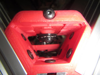
  7. Route the syncromesh up and around the idler, keeping it taught and not twisting anything.
  8. Finally, form another loop around the top peg
    1. It doesn't need to be too tight.
  9. Tighten the idler slider until the synchromesh is tight.
    1. When plucked, it should vibrate to a low note.
    2. Do not overtighten, you'll irritate your motor.


Mark 4 build - step 5: Connecting the Rods

The fifth step is to take the assemblies you have already created and attach them together.


Vitamins:

  • 12  * M5 flat-head screws, 25mm long.  The angled head is needed for the IGUS ends.
  • 12  * M5 nuts

RepRapped Parts :

Tools : 

  • 3mm ball-end hex key

Assembly:
  1. Find a nice big, flat table to work on.  I think it's easiest to place the hotend effector triangle-side down and work from there.
  2. Grab the hotend effector
    1. Insert nuts into each nut trap on the ball ends of the hotend effector - the nut traps in the triangle are for later.


    2. Screw a flathead screw through one end of a rod end assembly and into the hotend effector.
    3. Tighten it down, rotate, and repeat for each rod.
  3. Grab a Rail Effector Assembly.
  4. With the triangle side of the hotend effector on the table, the wheel side of the rail effector should be facing up for attachment.
    1. Make sure they all face the same way!
  5. Insert two nuts into the long nut slot on the top of the rail effector.
  6. Thread an M5 flathead screw through the rod end assembly attached to the hotend effector.
    1. Repeat this step for the other arm.  Parallel arms only, please!
  7. Repeat 3-7 for the other two rail effectors.


  1. Insertion.
    1. Remove the v-wheel sliders from the rail effectors.
    2. Place the hotend assembly ball-down in the center of the prism
    3. Attach each rail effector in turn.


Friday, June 7, 2013

Mark 4 build - step 4: Arm construction

Step 4 is to assemble the carbon fiber arms, six of which will connect the hotend effector to the rail effector.

Vitamins:

  • 1  * 325mm Carbon Fiber Square Tube, 8mm OD, 6mm ID
  • 4  * M5 nuts
  • 2  * IGUS KARM-05 rod ends

RepRapped Parts :

Tools :

  • Saw, if your rods aren't cut to length.
  • Knife for part cleaning - exacto or similar
  • Long tweezers - getting those nuts in is a pain.
  • Super Glue - thin cyanoacrylate adhesive 

Assembly:
  1. Cut your rods to length.  The best way to do this is a chop saw, table saw or similar with a repeatable stop - making all the rods the same length is pretty critical.
    1. Use a fine-tooth blade.  They're expensive, but worth it.  Mine was 80 tooth, on a 10 inch radial arm saw.
    2.  WEAR PROTECTION!  Eyes, lungs, ears and hands.
      1. Carbon fiber fibers flit about, and will take up residence in your lungs or eyeballs.
      2. Do I need to tell you why that's bad?
    3. Vacuum up all the bits BEFORE you take off your protections.
    4. Alternately, you can hand-cut with a hack saw; the rod ends are adjustable enough that you should be able to shore up the lengths.
  2. Clean the parts.  Where the rods insert should be OK, but the nut insertion hole is finicky.
  3. Assemble the rod ends.
    1. Take a KARM and thread a nut all the way down.
    2. Take a rod end and slip a nut into the long slot.  The slot is wider at the base.
    3. Screw the KARM into the nut in the rod end - tighten it down lightly.
    4. Do this twice - each rod has two ends :-)
  4. Place the rod end assemblies onto the ends of the rods.
  5. Tap the rod ends into place.  The square rod hole becomes hexagonal halfway up - you want the square rods to be touching this hexagonal transition.
  6. When the rod is all the way in, place a few drops of cyanoacrylate in to hold them in place.
  7. Repeat for the other 6 rods.
  8. Align the rods - I did this by inserting threaded rod through each rod end eyelet.  Adjust the rod ends 1/2 turn at a time, then tighten them down.
    1. Accurately measuring this length is crucial!
    2. Making sure it's the same length for each rod is also crucial!
    3. Write down your length, the firmware will need to know about it later.
    4. 400mm even is the design length with the given parts.


Saturday, June 1, 2013

Mark 4 build - step 3: rail effector assembly

By now, you have the rough outline of your printer, and even some motors mounted - the next step in the build is to put the rail effectors together, get some linear motion going.

Vitamins:

  • 3  * Delrin V-wheel kit (openbuilds)
  • 4  * M5 Round cap screws, 25mm long
  • 4  * M5 nuts

RepRapped Parts :

  • 3mm Ball-end hex key
  • Knife for part cleaning - exacto or similar


Assembly:
  1. Clean out the nut trap and cut away the onion skin from the Wheel Slider.
  2. Assemble the Delrin V-wheel kits - note, the metal shim goes between the bearings - it's not a washer.  Don't put the nuts on yet.
                                                 
  3. Insert the lock nut from one wheel kit into the Wheel Slider, then bolt on one of the wheels.
  4. Clean out the nut traps and cut away onions skins from the Rail Effector.
  5. Insert the other two lock nuts into the outermost nut traps
  6. Insert 4 nuts into the inner nut traps, two on the base and two for the wheel slider.

  7. Screw two round-head screws through the inner nut traps, all the way in.  These are for attaching the syncromesh later.
  8. Insert and screw in the Wheel Slider.  Screw down all the way.
  9. Insert and tighten the other two V-wheels.
  10. Test it on the rail!  You'll likely need to adjust tension on the wheel slider. 


It should look like an android head.  Note that you shouldn't install the IGUS ends yet.
Repeat for the other two assemblies.