Improvements:
- The new effector is much more compact.
- Much higher torsional stability
- Integrated Z-Min endstop (Experimental!)
- One fan per hotend
- Simpler hotend clamp
- Black.
Vitamins
- 3x M5x20 socket cap screws
- 3x M5 washers
- 3x M5x40 socket head cap screw - make sure it's got a smooth part on it
- 3x springs that'll fit around an M5
- 6x M5 nuts
- 1x M3x20mm screw
- 1x M3 nut
- 1x M3 washer
- 1x M3 spring
- 1-3 30mm fans
- 1-3 hotends (pictures are using the e3d hotend. It comes with 30mm fans, but they're not great. I used some old ones that blow harder)
- 1 tactile switch (digikey or just ask, I got a bunch of extras)
RepRapped Parts
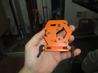
- Hotend Effector (https://github.com/paenian/bertha/blob/master/hotend_effector.stl)
- Tripleclamp (https://github.com/paenian/bertha/blob/master/tripleclamp.stl)
Assembly


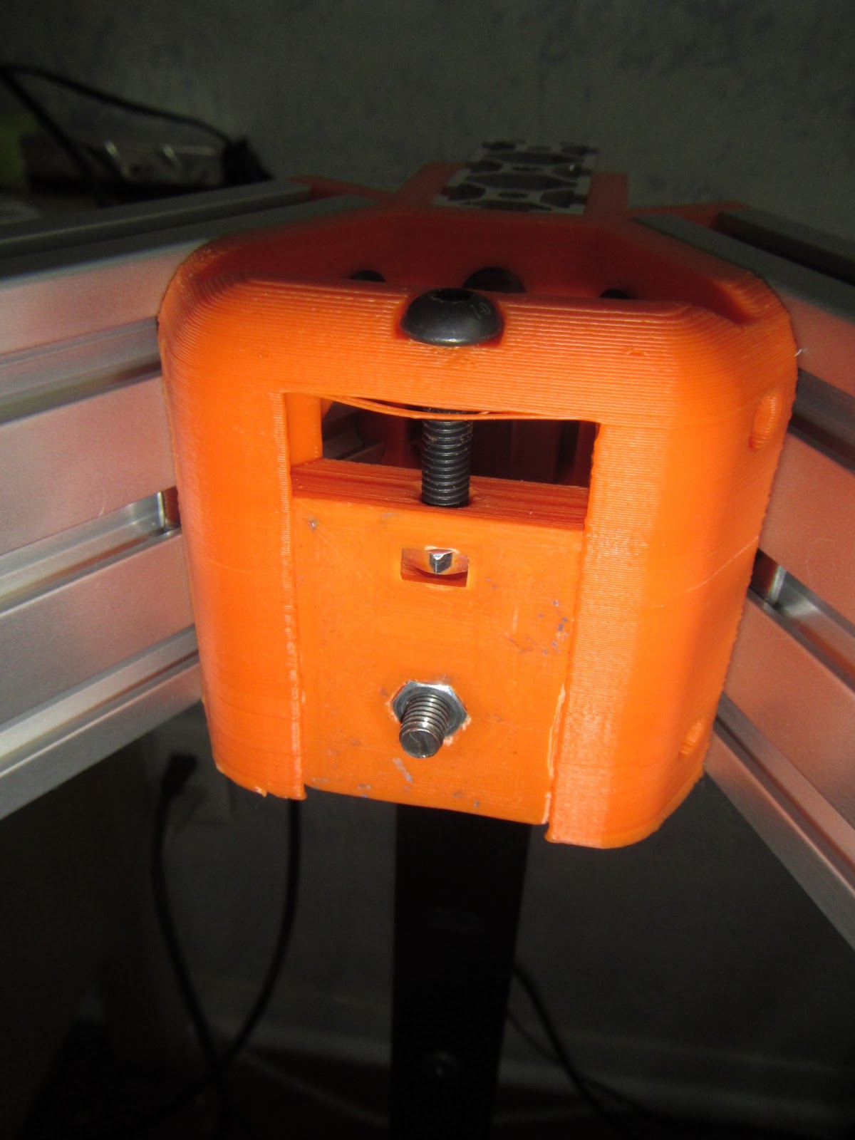
- Take the Tripleclamp first.
- Insert the M3 hardware into the center hole - nut into the nut trap, washers and springs above:
- Insert an M5 nut into all three nut slots, then loosely screw in the shorter M5 screws with washers.
- Take the longer M5 bolts and springs, and drop in through the top of the tripleclamp (the top is the shiny part). It should be a semi-loose fit.
- solder two of the switches leads, on the same side - you'll need to bend them sideways to get it in the hole, and also bust off the other ones. Make sure to test the switch - if you pick the two wrong contacts, it'll be always shorted.
- Insert the switch into the hotend effector, wires through the holes.
- Insert the three long M5 bolts down into the hotend effector itself. There are three nut traps inside the side holes, hidden away.
- Tighten lightly.

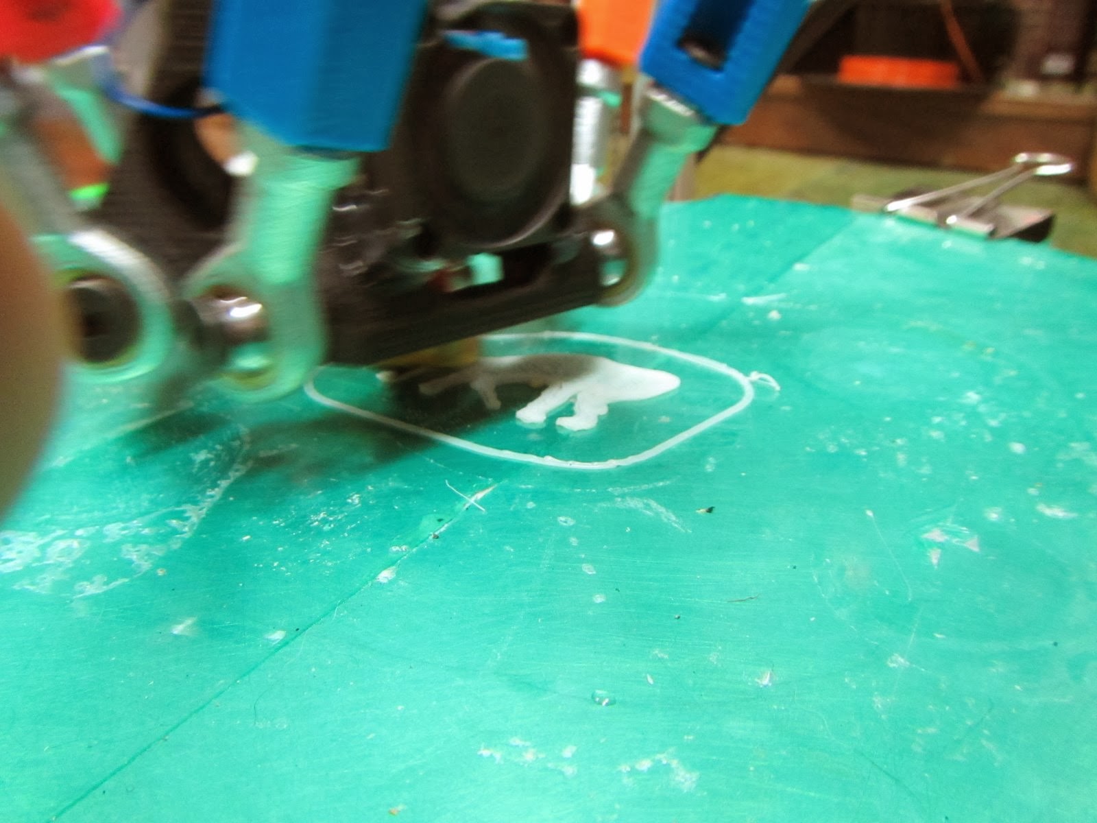
And there you have it. Hotends can be inserted now, as well as fans. If you use the E3d hotend, well, the fans don't fit in their slots - but you can hot glue 'em in just fine. Wire it up, and let 'er rip!
I am currently stress-testing this setup - running some long prints to shake it down. Next step is activating the Z-Min endstop, but that'll be another blog post.


