Sunday, May 26, 2013

Mark 4 build - step 2: Prism: assembly 1

Once the triangles are complete, you can construct the uprights for the bot.  It uses 2060 extrusion with OpenRail attached.  In the future, this may change to using v-groove rail directly.

Vitamins:

  • 3   * 1000mm 2060 aluminum exrtusion (misumi)
  • 3   * 1500mm openrail v-rails
  • 24 * T-nuts (included with openrail)
  • 24 * M5 by 10mm button cap screws (included with openrail.  Be sure to specify 10mm screws!)
RepRapped Parts:

  • No new parts, Just the brackets from the triangle assembly.

Tools:

  • 3mm ball-end hex key
  • Rubber or wooden mallet
  • Knife to clean parts
  • M5 tap


  1. Tap your extrusions.  This isn't necessary for this step, but it'll make adding feet much easier in the future.  I tapped the center hole of each end of the long exstrusions for good measure.
  2. Cut the openrail in half.  You should have 2 750mm sections.
  3. Pre-thread the T-nuts through the rails.  I used every other hole.
    1. Notice the v-sections interlocking.


4.  Slide the v-rails into the 2060 aluminum.  Lightly tighten a few bolts such that there's about 125mm gap at either end.
5.  Clean up the brackets - make sure that both top and bottom of each bracket is free of lips/ridges that could catch on the extrusion.
6.  Slide the rails into the idler triangle.  Carefully align the t-nuts in the brackets, and tap home with the mallet.  This step is tedious!  Go slow and make sure all the t-nuts slide in.
7.  When all three vertical beams are installed, repeat for the motor triangle.  Be sure that your colors line up!  Hint: You can flip the motor triangle to make the colors align.  You can't flip the idlers, which is why we started up there :-)
8.  Finally, loosen the rails and slide them tight against the idler brackets.  There will be a gap above the motors.
9.  Align the v-rails on the extrusion and tighten every screw.


That's me!


Bertha Mark 4 next to Mark 3.  3 looks bigger, but the print area will be about the same.

Friday, May 24, 2013

Mark 4 build - step 1: Triangles: assembly 3

The next step is to pop in the idler sliders.

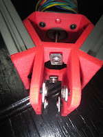
  • Assemble the bearing first - it goes on the raised impression, with a m5 nut on the back.  Tighten down.
  • Next insert the other nut into the rectangular slot.  It should be a reasonably tight fit.
  • Insert the idler slider into the idler bracket, with the bearing on the inside.
  • Drop the final screw into the hole on top of the idler bracket, then through the idler slider and screw it into the captive nut.
  • Done!
     

Monday, May 20, 2013

Mark 4 build - step 1: Triangles: assembly 2

  1. Tap your extrusions.
  2. Pre-thread your T-nuts.
  3. Slide the triangles together
    1. The plastic brackets are rather stiff (by design, of course), so the only way to get the extrusions assembled is to insert all of them at once.
    2. Place the three vertices rounded-side-up (make sure they're all the same vertex - motor or idler!) in a rough triangle.
    3. Place the extrusions between them.  Both extrusion and vertex are 60mm tall
    4. Insert the extrusions up to the first t-nut on all triangles.
    5. Slowly bring the three brackets together, sliding all three extrusions into all three brackets simultaneously.  You'll need to orient all the T-nuts properly as you approach the two rear nuts.
    6. When the extrusions are almost home, insert screws into the end plates and screw into the holes you tapped previously.
      1. Screw in both extrusions on the bracket before moving to another bracket.
      2. Make sure that there are no gaps!  After this step, the triangles should be rigid.
    7. Tighten the uppermost t-nuts on all brackets - use the ball ends.
    8. Flip the triangle carefully, then tighten the current uppermost t-nuts.


    9. The screw in the center goes in first


             into the holes you tapped in step 1.


    10. Tighten the middle t-nuts from inside the triangle - it's a bit tight.
  4. Install the motors
    1. Motor going in.
    2. If you're on the motor mount side, screw in the motors.
      1. The idler triangle is done for now.
    3. Use the M3 screws and washers, tighten down with the 2mm hex ball-end.
    4. It's easiest to do the top two screws of each motor, then flip the triangle and do the new top two. 


That's it for step 1.  At the end, you should have two rigid triangles, one with motors and one with holes for the idler slider.  Step 2 will install the openrail towers, completing the frame for the machine.


Mark 4 build - step 1: Triangles: assembly 1

Spliting posts, they get unwieldy with the web poster.  If anyone can recommend an offline poster I'd be interested.

Once you have the tools, plastic and vitamins gathered, assembly can begin!
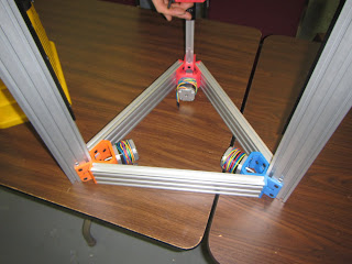
These are what we're building in this step:


  1. Tap your extrusions.
    1. There are three round holes on each end of your extrusions - the middle hole of these must be tapped.  They'll accept an M5 tap straight from the factory.
    2. Be sure to use thin oil for tapping - re-oil the tap a couple of times during the tapping.
    3. One turn forwards, half a turn back.  Aluminum is soft, but don't overdo it.
  2. Pre-thread your T-nuts.
    1. This is tedious, but it's a lot less tedious than trying to move the nuts into place afterwards.
    2. You'll need 12 T nuts and 14 M5 screws - the two extra screws are for the tapped holes.
    3. The channel takes 6 t-nuts, then each flat side takes three more.
    4. Insert the screws all the way through the holes, then twist a t-nut on one or two revolutions.  If you go too far, the extrusions won't be able to slide on.
    5. Loosely fit T-nuts
          
      8 T-nuts on the inside, four in the channel.


Mark 4 build - step 1: Triangles: parts

I've started on the build for Bertha Mark 4, along with several other folks at the Nova Labs Makerspace in Reston.  So, we'll need build instructions!  Here's the first step, building the triangles.  I'll post step-wise Bills of Materials, then at the end do another sum-up and make sure that it's correct.

Vitamins:

  • 6   * 350mm 2060 aluminum extrusion (Misumi)
  • 84 * M5 by 10mm flat head cap screw (Open Builds Part Store) - 14 per vertex
  • 72 * M5 Stamped T-nuts (open builds) - 12 per vertex
  • 12 * M3 by 10mm button cap screws
  • 12 * M3 washers
  • 3   * Nema 17 motors 
  • 1   * 625 bearing
  • 2   * M5 by 25mm button cap screws
  • 2   * M5 nuts
RepRapped Parts:
Tools: 
  • M5 by .80 Tap
  • Tap Handle
  • 3mm Ball-end hex key
  • 2mm Ball-end hex key
  • Knife for part cleaning - exacto or similar
Trust me on the ball end thing - most of the screwholes will get covered up as you build, and space is tight.  I've ensured that it can be assembled just using the short ends of the hex keys, but it would take a toll on your sanity.  You can use any m3 screws that are 10mm long, but the m5 flat head screws are necessary for clearance on some of the M5 partsNote that the hex keys are smaller on button and flat head screws.


Wednesday, May 15, 2013

Mark 4, finally.

The Mark 3 design is essentially complete, but it lacks rigidity - the long vertical smooth rods flex far too much, which is exacerbated by the relatively short arms.  The closer the arm is to parallel, the more force is exuded onto the tower bars.

There were also issues with the torsional skew of the machine as well as normal XY skew.  Although that was solved to a large extent with the large boards, it made the machine rather cumbersome, by which I mean heavy.

Some of the parts have started to arrive - I'll be posting initial assembly instructions and BOM shortly.  There will be another, more professional set of instructions after I've built the first machine, but I wanted to have something out there for the adventurous.


Monday, May 6, 2013

Bertha 3, last historic post

 The final improvements moving up to Mark 3 were adding an LCD and hiding the electronics and power supply below the bed.  This is almost entirely for style; I also cut some designs into the uprights to polish it up a bit.

It's hard to get a good closeup of the bed.  I don't have any pictures of the entire underside, either... I'll flip the machine over and take a picture eventually.


Shot of the front, with designs.
 I did print an enclosure for the LCD also, just hadn't yet installed it.  Also added some wheels to the front so I could move it around more easily.
 Underneath I made a mount for the Arduino Mega - the mega is clipped in, box is screwed on, and the fan gets zip-tied to the top.  I use a twist tie on the other side so I can flip the fan back as needed.  Box is hanging out on Thingiverse.
 Front of the box, and shows the tiny power supply bracket.  It was pretty tight getting everything down there.

Finally, video of the final machine printing.  Later I'll start posting about Bertha Mark 4, design and decisions I made about it.  Those extrusions are 400mm long, and rather strong - but I'm not planning to use them in anything.

I printed them to test sizes/designs for Mark 4; it'll be made with actual aluminum extrusions.  Despite the wobble, the pieces came out quite straight.
 

Friday, May 3, 2013

Bertha Mark 3 heated bed

double-posting to catch up.  For Mark 3, I added a heated bed, an LCD and an SD card, and I hid all of the electronics underneath the heated bed.  Heated bed info is a bit weak, so I figured it deserves its own post.

For my heated bed, I settled on power resistors.  I used a 12->24V upconverter as well, which I do not recommend - too many cumulative losses.


This is the initial test.  Resistors taped to an eighth inch aluminum plate, on top of some plumber's heat cloth - Carbon wool.  Good insulator, relatively cheap, not as nasty as fiberglass.  You can see the fan running on my converter - it uses two transistors, both of which get quite hot.

I used 6 5ohm resistors, in parallel pairs giving (5+5)/3 = 3.333 ohms resistance.
V=IR gives us 24V/3.3333ohm = 7.2 amps, total wattage = 7.2x24 = 172 watts, which is plenty for this tiny plate.


I was able to reach 120C on this plate.  Pro tip: a cheap IR thermometer won't read aluminum, too much bounces off.  Put a piece of tape on it and read that instead.

The converter I used was an Ebay special, similar to this guy: http://www.ebay.com/itm/10-32V-to-35-60V-DC-Converter-Power-Voltage-Regulator-/260985897805?pt=LH_DefaultDomain_3&hash=item3cc3f8c34d

it's a 10~32V to 35~60V DC Converter Power Voltage Regulator.  Note that it maxes out at 5 amps output - giving its max rated wattage of 120 watts at 24v (24*5=120).  So I fiddled with the pot on the back, upping the output voltage a bit.

I also made a nice box to slot it in.  This is what RepRaps are for!  Designed in about half an hour, to fit the exact converter and fan I had on hand.  Design is up here: https://github.com/paenian/rostock-redux
It fits!  And this was on the first try, too.  The connectors on the other end were tight, but it worked well enough.
The bed, mounted before I attached heater resistors to it.  It's a large piece of 1/4" aluminum plate, cut with a hand-held circular saw.  Use a guide and a blade with lots of teeth, and go slow - like cutting frozen butter with a warm knife.
Such a nice bed.  Good thermal stability.  High environmental losses, though.
The bed's mounted on sprung screws driven down into the aluminum reinforcements.
I mounted the resistors to the bed with small screws, and covered it with carbon wool.  It works up to about 80C, as long as the fans are running that is.  The aluminum dumps too much heat into the air to get any hotter.


My next heated bed adventure will be using glass with Nichrome wire - it's the same principle, really, just with longer, smaller resistors.

More Mark 2 photos/vids


Just a couple more pictures of the Mark 2 Bertha, and a big point:


A RepRap isn't a printer until it's reliable.  One of the first things I do with a new printer design is queue up a ridiculously long print - a torture test, to see which component is the weakest.  What will break first.  So even before I had the bed sorted out, I printed a giant Klein bottle.  It's about 15" tall, and it took two days on this machine.


Of course, you can't always print giant things for tests.  My usual test object is this frog:


It's small, complicated, stresses retraction, overhangs (under the chin) and overheating the top (eyeballs are their own layer).  If you can print a frog nicely, you can print most things.  Plus, whenever I show off the machine I can give something away.

And finally, a video.  My wife likes skulls and owls, so, I printed her a small owl on a larger-than-life skull.

Thursday, May 2, 2013

Bertha Mark 2

 After Bertha printed, I realized that her rigidity was sub-standard - so I dismantled her, and started adding braces.  The first to go on are these aluminum angles - preventing the triangles themselves from rotating during printing.
 I slotted some 2x3s for the base, carving out where the aluminum angle intersected.  And yes, 2x3s, not 2x4s - I dismantled a fireplace surround and it was just full of 2x3s.  It's a little bit of nostalgia baked into the machine.
 Ah yes, carbon fiber arms.  I actually had added these previously, since the shipment finally came in.  Much stiffer than basswood!
 Full bot coming together.  I spent a lot of extra time sheathing cables.  This machine looks too good to leave wires hanging about.
 The vertical panels are laminated wood shelves - very flat and stiff, but kind of heavy.  Bertha actually got her name somewhere around here, because it was becoming increasingly difficult to move her about.
Yeah, my printer's a stud.  My wife Ruby does the painting and staining for all of my projects, including Bertha.  I asked her to paint this stud half blue and half red - thinking of course to make the whole printer have a red half and a blue half.  Instead, the back and bottom sides of this board are red.. which is OK I guess.
 Mounted the bowden.  Here I've switched from 3mm filament to 1.75mm, and am using Airtripper's bowden.  Not a bad setup.

 Noodle!  Electronics mounted inside as well, keeping everything easy access whilst I'm playing with it.  Also notice the red strap - that's what's holding on my janky computer power supply.
 First print!  I think.  Still using my astonishingly uninspired bed.  This is the first iteration of the printer that built big things - large klein bottle, giant skull with an owl, my first attempts at wind turbines.  It's a bit rough with the poorly designed bed, but functional enough.  It had sat idle for a couple of weeks, so I wanted to get some functionality back - this thing's too big to just sit in the corner and mock me.  So yes, enjoy some videos!


Another reason it sat so long is because I was building my print cave... you may notice that the floor is different, and that there are walls - it's still in the basement, but in a nicely insulated room.  Having a posh workspace is pretty key.